 BEAR's
TS-440s
AM Mods (v1.1.06)
BEAR's
TS-440s
AM Mods (v1.1.06)
Obviously, all these approaches have some similarities.
This is the biggest difference here: it looks like I have a source for the hard-to-find improved filter for the CF2 slot - with improved skirt selectivity and better shape factor than the stock versions, and in various bandwidths suitable for AM phone!
---> Email me for details and filter availability !! <---
New UPDATES!! - LTSpice Analysis -
| Schematic/PCB View | MODIFICATION: | |
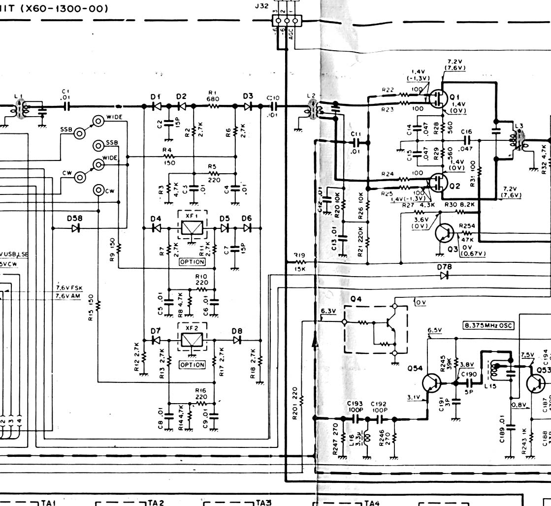
| Overview- | There are two parts to getting better AM performance from the TS-440. The first is the analog audio chain; the mic amp and driver. The second is the IF section filters; the Ceramic 455kHz. Filter(s) or "CF", and the 8.33mHz. Crystal Filters or "YK" filters - named after Kenwood's part number designation of YK-XXXX. | |
click for schematic page |
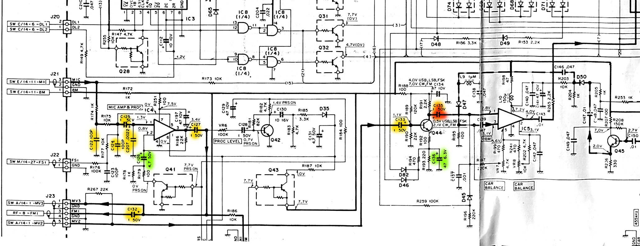
Mod to mic input circuitry:
Essential: Change C135 from 0.1ufd to 1.5ufd. Optional: C125/C127/C132/C133 from 1.0ufd to 10ufd or similar |
|
| note: Orange hi-lite = essential change; yellow = suggested; green = under consideration | ||
| Discussion - | C135 is the main bottleneck in the LF end of
the xmit audio chain. In general terms the effect of doubling the value of
the cap is to lower the LF rolloff by one octave. How much LF you need or
want in your rig depends on your view of it - I feel that response below
~40Hz. is entirely pointless in an AM rig. Likely ~60Hz. is a more
practical LF limit. C124 & C207 double as a 2 pole HF rolloff, with
C207 dominating, and an RF eliminating filter for the mic preamp. Some
mods suggest removing these caps, I'd reduce their value to to point where
they no longer effect the HF response, not remove them entirely.
IF you have no CF in the xmit mode at all, then opening up the HF response of the rig is likely not a really great idea at all. It seems that something between a ~5kHz and 10kHz maximum bandwidth in the audio chain is appropriate. Remember that an AM 5khz. audio bandwidth is a 10khz. wide RF signal. (+ & - 5kHz). The values for C125...etc. are suggested by a ham who has alos worked on the rig. One should be skeptical of the 10ufd values resulting in too low a LF limit. Here's why - C126 is 4.7ufd. The role of this cap is to drop the LF response of the opamp to unity at some frequency. So, by adjusting the value of C126 one can control the ultimate LF rolloff frequency of the mic amp. There is no purpose to supplying audio at frequencies below the LF rolloff set by C126. Ideally, one would put the other LF rolloffs at or above this rolloff frequency - this creates at least a 2 pole rolloff (12dB/oct) as compared to a 1 pole rolloff (6db/oct) at that LF frequency. Since the impedances related to the other caps appear (based on simple inspection) to be similar to the resistance "seen" by C126, making the other caps larger than C126 is probably not the right idea. I suspect that the value I used for C135 - 1.5ufd - is probably about correct for all these caps. If we make the assumption that the original factory LF rolloff was set to 100Hz., then putting in 10 x 1ufd = 10ufd coupling caps puts the LF rolloff at 10Hz.!! Imho, too low - so it is important to get this right and not shotgun the thing... On the other hand, IF the 0.1ufd cap at C135 was used as the only limit to roll the LF at 100Hz. then increasing the 1.0ufd caps to 10.0ufd is likely pushing the LF too low. But it looks like the 0.1ufd cap looks at 220kohms, while the rest of the circuit looks at more like 10kohms... so they are probably scaled similarly in terms of frequency. Guess this needs to be looked at carefully, eh? I used a Tantalum cap was for C135. The advantage to them is that they are small for their capacitance/voltage rating compared to the little electrolytic cans, an easy fit. Also, Tantalums are known to impart a nice "smoothed" sound in audio circuits - not a bad thing for AM transmit audio!
The way to resolve this issue is to actually sweep the audio section and see
what the LF points actually are, set the caps appropriately for each cap
position in the circuit. Otherwise, one can analyze the circuit's impedances and
scale the caps that way.
|
|
| LTSpice UPDATE! | Ok, as of 1/16/06 I have run a number of
LTSpice simulations of the actual mic amp circuit. This is the schematic
of the Stock circuit.
It is taken from the service manual's schematic. This is the circuit up to
the second stage - which is Q44. This is the graph
of the frequency response.
(the component numbers DO NOT correspond to the Kenwood circuit, nor do they necessarily correspond between PSpice examples, but they should there!) Note that the HF rolloff is ~10kHz and the LF rolloff is <10Hz.!! This was quite surprising, and unexpected. So, IF there is a "bottleneck" in the audio chain it is not here! (a generic LT single power supply opamp was substituted
for the unusual Kenwood part) I also ran many tests with altered component values and circuit variations. I tried looking at the effects of circuit values on HF rolloff. Including placing a cap around R2, adjusting or eliminating the various input shunt caps... none of these efforts significantly altered the HF rolloff for the better. With the stock rolloff @10kHz. there is little more that could be accomplished that is beneficial other than increasing the slope of the rolloff above 10kHz. To that end, this LTSpice simulation was created which incorporates a third order LC network at the input. The values are impractical, but the graph is instructive. Note the improved HF rolloff. Wouldn't that be nice? No values of C1, C4 or C6 were found that successfully raised the LF rolloff point in a worthwhile way, or provided better LF rolloff slope. |
|
| LTSpice Summary | Based on these results, which may or may not be
definitive, the changes suggested by this other ham for this part of the
circuit are not necessary, and may actually be detrimental. It would
seem that the bottleneck as far as LF response and/or HF response
is likely in the following stage, Q44, or thereafter. (see
below for more on this...)
With respect to HF rolloff, it is not an issue with the stock circuit - response essentially flat to 10kHz. is more than sufficient, and actually might be a bit much. Removing the input shunt capacitors is not recommended based on this simulation. The input shunt caps are most likely there for ironclad RF immunity. (and a little HF rolloff) Two caveats: Actual impedances & resistances may or may not be different in the actual circuit as compared to the simulation - however varying several artificially imposed load resistances over a fairly wide range in simulations not illustrated here did not vary the results significantly. So, if the LTSpice simulation is good, the results are valid. It still makes sense to actually sweep the circuit in-situ, and confirm that the LTSpice results correspond to the real circuit. It is always possible that it is different. I decided to try the simulation, since it would be "faster" than digging into the rig and setting it up on the bench. Not so sure about that! But regardless, the LTSpice makes it trivial to experiment with the circuit and the values of components, which is a big benefit.
|
|
click for schematic page
|
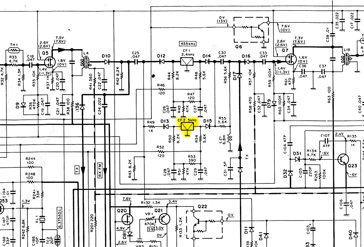
CF Filter Mods:
Change the stock CF2 for a higher performance CF of proper bandwidth for AM. Available as a direct solder-in replacement are filters at +/- 4.5kHz and at +/-6kHz. Both have superior shape factor/skirt selectivity. Also, an improved skirt "stock filter", nominally +/-2kHz. can be had... as well as an improved +/-3kHz version. (see additional info, last section) |
|
| Discussion - | The 440s uses two sets of filters Ceramic
Filters ("CF") @ 455kHz. and "YK" series Crystal Filters at
8.33mHz. CF2 controls the maximum receive bandwidth in SSB and AM! In SSB and if installed, CW, the YK- series crystal filters which are sharper and narrower up at 8.33mhz. are doing the selectivity job. In AM, the "YK" filters are bypassed completely. The job falls to the 455Khz. CF filters. The stock filter ("CF1") is an inferior filter with poor shape factor and skirt selectivity. Too make matters worse for AM it is also only ~+/-2kHz ("or more" as the service manual specs it) with the skirts at only 40dB down that being at a width of 7.5kHz. The problem here is that the top end of this curve is too really too narrow for good sounding AM audio. The solution is to replace CF2 with a higher quality filter. Available as a direct solder-in replacement are filters at +/- 4.5kHz and at +/-6kHz. Both have superior shape factor/skirt selectivity Note: the block diagrams in the Service Manual indicate that CF1 is used on xmit while CF2 is used for AM receive. CF1 is nominally +/- 1.1 - 1.3kHz. Too narrow for AM. I have yet to take the time to determine if CF1 is in fact used on AM transmit. IF SO, it would be important to enable the pin-diode switching in the AM transmit mode when the AM filter is enabled on the front panel, or via the selection of AM on the front panel mode switch. I have yet to fully investigate this issue. |
|
| Other options - discussion...
|
Clearly, if the CF1 is used on AM xmit, then it
must be modified so that CF2 is used, not CF1. One answer might be
to switch out CF1 for a new wider "CF2" type filter. The problem
with this is that the Crystal Filter farther up the line that is used for SSB
receive is NOT used in the transmit mode at all!
So, the bandwidth of the transmitted signal is more or less dependent on
the bandwidth of whatever CF is being used. Unless you really want a wider
SSB signal, changing this would not be a good idea.
- Another option revolves around retrofitting a "wide" YK AM filter in addition to the existing slots in the Crystal Filter area ( I have the optional 2.3 wide Xtal filter and the CW filter in the existing holes). IF you did not have one of the optional filters installed, one could modify the way the PIN diode switches are activated so that the new "YK AM" filter is activated in AM receive mode, either by the "wide" switch or via the mode select. This would solve the receive end if a wide CF2 was installed, but not the narrow CF1 xmit issue! - In lieu of the xtal filter mod suggested above, one could consider also cascading two new CF2 filters, for fairly extraordinary skirt selectivity. For example one could use a 4.5 and a 6.0 resulting in an ultimate skirt selectivity far in excess of the 60dB max available from a single one of these high-performance Ceramic Filters. Doing this would require a buffer amp to make up for the insertion loss of ~6dB and to isolate the two filters. The good part is that at 455kHz. almost any good "video" opamp will be more than sufficient for the job. A small "sister board" would be required to hold the two filters - I believe there is sufficient clearance to mount the things between the top cover and the components on the board... - Yet another way to do things would be to use the "Voice" push button on the front panel to actuate a switch between AM "wide" (the +/-6kHz. CF2) and AM "narrow" (the +/-4.5kHz CF2). This might be a nice option, since having tested the 6kHz. version in CF2, it sounds great but is a bit wide when the band is busy. Doing this would involve some internal wiring between the pushbutton, the power supply over to some new pin diodes and related components.
|
|
| Additional Comments- | One ham who has worked on this suggests mods
to the Audio output
section of the receiver. These include increasing the value of various
audio caps. Thus far I have not found that the audio section lacks LF
response when used with a speaker with a good extended LF response. You
may feel otherwise, in which case consider those mods from his site.
Also, he suggests changing some caps that are apparently in the squelch circuit - around Q12, but at least at this point they seem to be of limited value, if any. I may have simply overlooked some important connection, of course! :- ) |
|
| Update Comments 3/13/06 | The bottleneck on the HF side of the xmit
audio appears to be elusive so far... At first it looked like F2 on
the RF board (+/-3kHz, shallow skirts...) was the culprit. Closer
examination says that it's only on receive that this filter operates -
something to consider for receive, but not xmit!
I'm still searching for the HF rolloff in the xmit audio. Important: The CF2 filter may or may not be switched in during xmit, it is entirely unclear from merely looking at the schematic(s). If it is not switched in during xmit, this would account in full for the restricted HF response during xmit! That means the CF1 - SSB filter is being used for xmit. Probably the best way to determine this is by testing the voltages on the PIN diodes with the rig activated for xmit, and I have yet to do this. Changing the logic to make the CF2 active during xmit should be feasible, if that is what is needed. After trying the +/- 6kHz filter in CF2 for a while, my conclusion is that it is too wide. The +/- 4.5kHz filter is far better. Perhaps even this one is still too wide for use when the band is very active. The original stock filter makes it easier to eliminate adjacent channel chatter. The "new" version of the 'stock filter' has better skirts, and might be best in terms of a "tight" filter. The 4.5kHz filter sounds great when the band isn't crowded, and on broadcast signals. The modification of switching in a 6.0kHz "YK-XX" filter would be nearly ideal as an optional filter to switch in with the new 4.5kHz filter, imho. (The "YK-XX" filters work ONLY on receive.) Or, the modification of switching in the "new" better skirt stock CF2 filter would be an alternative, or good in combination with the YK-XX filter. Either way this requires the building of a sub-board with PIN diodes, probably the replacement of the Voice pushbutton with a push-on/push-off type, or the use of JK flip-flops and an indicator LED to show which filter is in for one or both of these filters. There is no on-board provision for them in the rig. Ideally, one would switch the optional filters in only on receive. This requires a bit more work, as one would need to grab a xmit logic control line to enable an AND gate for the new PIN diode filter switching in addition to the JK flip-flop circuit. Regardless, I don't see much if any benefit to trying to shoehorn in a Collins mechanical filter, given the performance and availability of the drop in place Ceramic Filters (CF2). |
|